Installation |
Installation |
Calculator |
Processing |
Communications |
|
C'est une carte pour réseau RNIS (Numéris) qui disparaissent pau à peu. Elles pouvaient gérer sur la même ligne de la voix, des données, de la vidéo et du fax. Elles embarquaient en effet un processur de chez INMOS, le plus souvent le Transputer T400 à 20MHz ainsi que 1Mo de RAM. Leur tâche étaient de gérer les échanges. Trouvée sur Ebay à un bon prix, j'ai entrepris l'installation! |
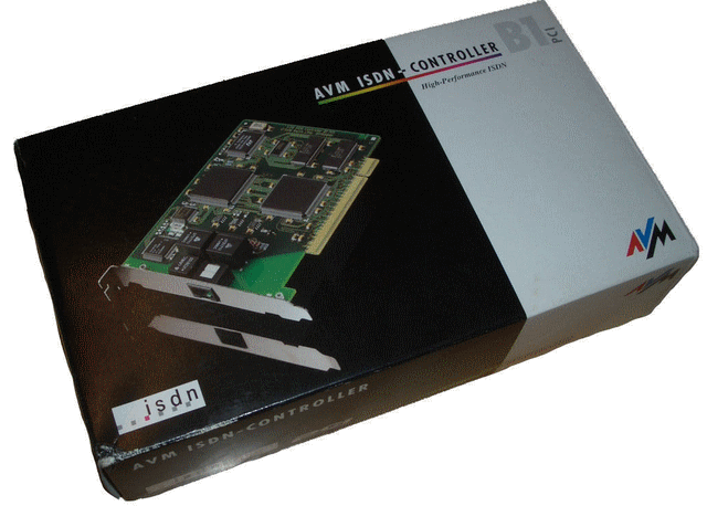 |
They are cards to communicate on a ISDN network for both voice, data, video and fax on the same line. They came with a CPU from INMOS, mostly the Transputer T400 clocked at 20MHz that could rely on 1MB RAM. Their task was to manage the transferred data. Found on Ebay for a very good price, I started the installation. |
Bien sûr, ces circuits donnent toute leur puissance dans une architecture multiprocesseur, mais c'est l'occasion d'en appréhender la programmation, en particulier avec le langage OCCAM développé par INMOS. On dispose également d'un compilateur C. |
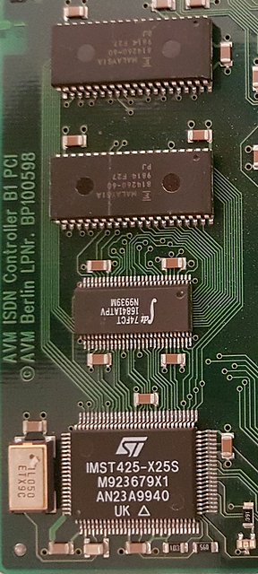 |
Of course, those chips show their full potential in a mutltiprocessor architecture, but that was the occasion to start learning the OCCAM language designed by INMOS. A C compiler is also available. |
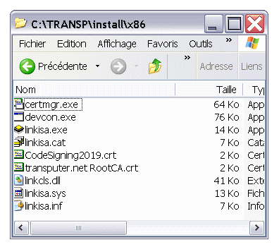
On trouve sur sa page tansputer.net de nombreuse documentations et téléchargements. C'est parti pour l'installation. Il faut d'abord créer une interface pour dialoguer avec le Transputer. Créez un dossier avec les fichiers utiles à cette installation. Puis exécutez les commandes ci-contre. Le fichier d'installation s'appelle linkisa.inf même pour les cartes PCI, ceci n'est pas une erreur. |
rename c:\windows\inf\avmisdn.inf to avmisdn.in_
delete c:\windows\inf\avmisdn.pnf

certmgr.exe /add "transputer.net RootCA.crt"
            /s /r localMachine root

certmgr.exe /all /add "CodeSigning2019.crt"
            /s /r localMachine trustedpublisher

copy /b "linkcls.dll" "%SYSTEMROOT%\system32"

devcon.exe dp_add "linkisa.inf"
|
On his page, tansputer.net, you'll find lots of informations, documents and software. Now, the installation itself. First we need to create the interface to exchange data and commands with the Transputer. Create a folder with those files. Execute the commmands shown. The installation file is named linkisa.inf even for the PCI boards, this is not an error! |
|
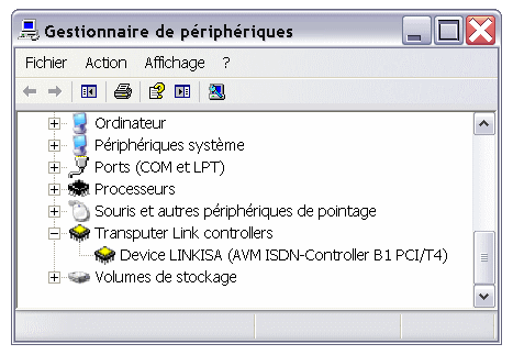
Le transputer doit apparaître comme sur la figure ci-contre. Reste à installer l'interface logicielle de programmation... |
|
You should see the Transputer as shown! Now it's time to install the programming tools. |
|
Ces fichiers BTL sont les exécutables du T425 qui lui seront envoyés. Ouvrez ensuite le dossier d72uni, nous allons nous intéresser à BAVM.BAT et D72WIN.CMD. |
assoc .btl=Transputer.Bootable.File ftype Transputer.Bootable.File="%ISERVER%" /SB %1 %* 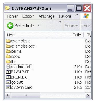
|
Those BTL files are the executables that will be sent to the T425. Open the d72uni folder, we'll now work on BAVM.BAT and D72WIN.CMD. |
|
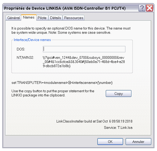
Retournez dans le Gestionnaire de Périphériques et demandez les Propriétés du Transputer. Prenez l'onglet Names et cliquez sur Copier pour recopier le nom de notre matériel. Ouvrez BAVM.BAT et dans la ligne Set TRANSPUTER=remplacez l'ancien nom par celui que nous venons de copier, puis sauvegardez. |
|
Go back into the Device Manager ans ask for Properties of the Transputer. Select Names and clic on Copy to get the name of your device. Open BAVM.BAT and in the line Set TRANSPUTER=replace the old name with the one you've just copied, and save the file. |
La cible:
%windir%\system32\cmd.exe /K
  c:\TRANSP\d72uni\d72win.cmd
    c:\TRANSP\d72uni\bavm.bat

Démarrer dans:
c:\TRANSP\d72uni
|

|
The target:
%windir%\system32\cmd.exe /K
  c:\TRANSP\d72uni\d72win.cmd
    c:\TRANSP\d72uni\bavm.bat

Start in:
c:\TRANSP\d72uni
|
|
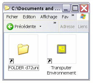
J'ai créé également une icone pour accéder au dossier d72uni. |
|
I also added a shortcut to the d72uni folder. |
|
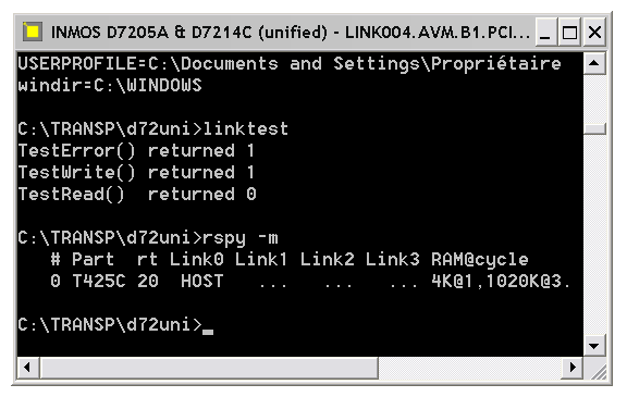
Pour commencer, testez ceux-ci: linktest rspy -mOn y lit que le T425C dispose de
|
|
As a starting point, try those two: linktest rspy -mYou can read that the T425C has:
|
|
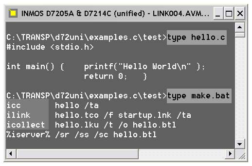
|
|
|
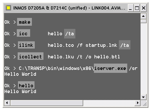
Le paramète /ta spécifie le processeur cible.
|
|
The /ta parameter specifies the target CPU.
|
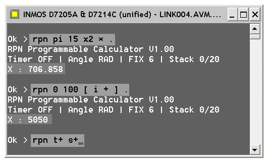
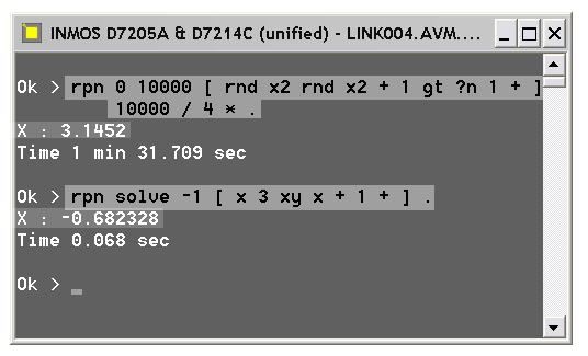
RPN ... liste d'opérations ... ENTERLa première ligne calcule La seconde calcule  . .
La dernière règle les modes t+ (affichage du temps) et s+ (silent, moins d'affichage). |
|
RPN .. operations list ... ENTERThe first line computes The second line computes  . .
The last one sets mode t+ (time display) and s+ (silent, less verbose). |
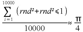
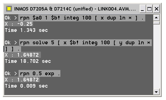
Puis on résout l'équation |
|

Solving for x with |
 . .
La seconde cherche la valeur x de la borne supérieure qui rend l'intégrale nulle 
|
|
 . .
The second searches the upper limit x that makes the integral equal to zero 
|
|
Merci encore à Michael Bruestle qui a été un beta-testeur et a suggéré des modifications pertinentes.
Vous pouvez télécharger ici la documentation, les sources et exécutables pour Transputer ainsi que pour Atari. |
Download RPN for Transputer Download RPN for Atari |
Thanks again to Michael Bruestle that was the beta-tester and that suggested many pertinent modifications.
You can download here the documentation, the source code and executables for Transputer and for Atari. |
| Le processeur fonctionne avec une pile interne de trois registres 32 bits nommés A, B et C. Le principe
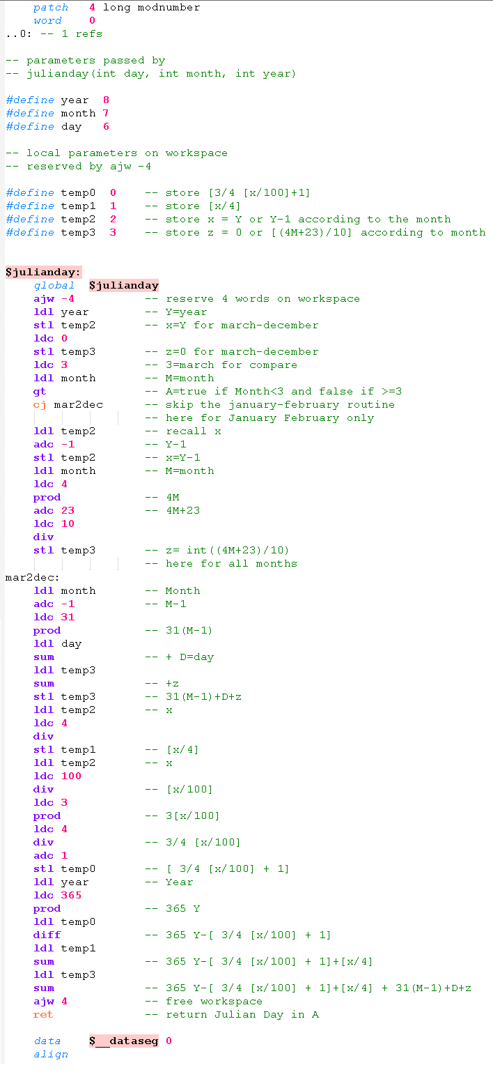
est celui d'une calculatrice RPN ou du langage FORTH. En plus de ces trois registres, les paramètres des fonctions sont passées par une pile descendante en mémoire pointée par un quatrième registre appelé Wptr (Workspace Pointer). Le processeur a été conçu pour optimiser les fonctions les plus utilisées (addition, lire ou stocker une valeur en mémoire, saut...), celles-ci n'utilisent qu'un octet. Pour les autres, plusieurs octets peuvent être nécessaires. Le programme ci-contre est la routine assembleur appelée dans un programme en C. Le programme calcule le nombre de jour de vie d'une personne selon sa date de naissance. Pour cela, j'ai écrit en assembleur la procédure qui transforme une date en jour julien. Au dessus est indiqué l'appel en C, trois paramètres seront passés sur la pile Wptr. En plus de ces trois paramètres, deux autres informations système sont nécessaires sur la pile qui occuperont les words 0 et 1. De ce fait, mes paramètres day, month et year deviennent les words n°2, 3 et 4. Mais, ma procédure nécessite 4 words de stockage temporaire qu'elle réserve sur la pile par ajw -4. Mes paramètres sont décalés de 4 et deviennent les words 6, 7 et 8. Les paramètres temporaires sont les words 0, 1, 2 et 3. Ceci explique les lignes #defineCeux réservés par le système ont les numéros 4 et 5 et ne seront pas accédés. Chaque ldl ncharge en A la valeur du word n en décalant A-B sur B-C. Chaque stl nstocke la valeur de A dans le word n. Les autres instrcutions utilisées sont: ldc npour charger une constante dans A. adc nqui ajoute n à A. sum, diff, prod, divpour les opérations. A la fin de la procédure, le résultat du calcul se trouve dans A, c'est la valeur renvoyée par la fonction. Important: ajw 4permet de libérer la place occupée par les registres temporaires. |
|
The processor works with a three-32bits-words stack named A, B and C. This is similar to a RPN calculator or to the FORTH language. Functions pass their parameters into a second descending stack in memory pointed by Wptr (workspace pointer), another register. The internal conception of the processor has been optimized as the most used instructions (such as add, store value, load value, jump...) only require one byte. Other instruction may require more bytes. The program presented here is a function in assembly language that is called from a C program. Above is the binding of the function. The program computes your age in days knowing your birthdate. To do that, my function computes the Julian day of a date. When a function is called, two system parameters are passed on a workspace in words 0 and 1, and additional parameters, such as day, month, year, start at words 2, 3 and 4. But, my routine requires four words as a temporary storage reserved by ajw -4on the workspace. Everything is shifted up four positions. So day, month and year are words 6, 7 and 8. And the temporary integers are on words 0, 1, 2 and 3. This explains the lines #defineEvery ldl nload in A the value of word n shifting A-B to B-C. Every stl nstore A into word n. The other main instructions are: ldc nto load a constant in A. adc nto add n to A. sum, diff, prod, divfor the arithmetic operations. At the end of the function, the result is in A, that's the returned value. Important: ajw 4frees the space of temporary words. |
Pour la compilation:
|
1) ICC dol /ta 2) ICC /pp julianday.s >temp.s 3) ICC /zs temp.s /ta 4) ILINK dol.tco temp.tco /f startup.lnk /ta 5) ICOLLECT dol.lku /t /o dol.btl |
For the compilation:
|
|
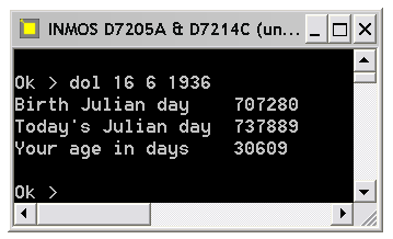
Au 7 avril 2020, il a vécu 30609 jours! |
|
As the 7th of april 2020, he lived for 30.609 days. |
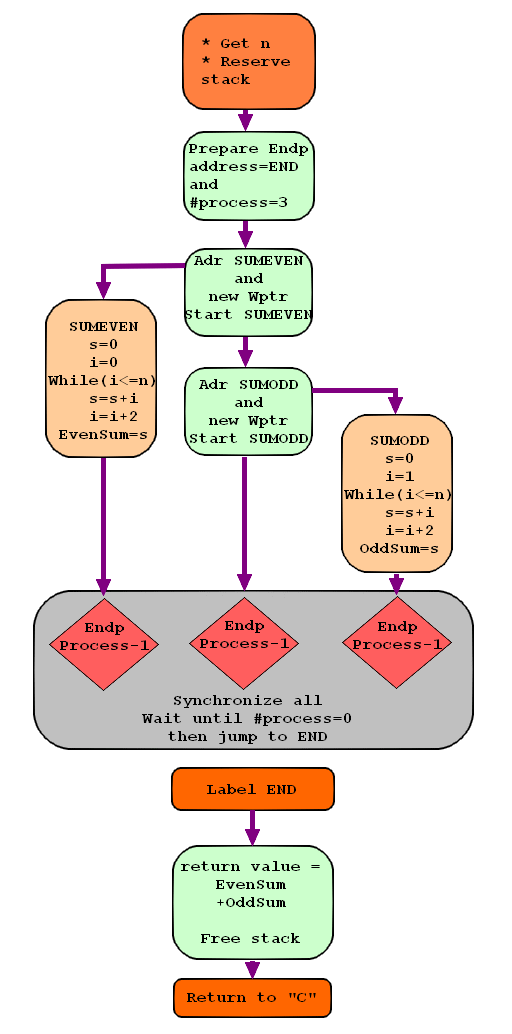
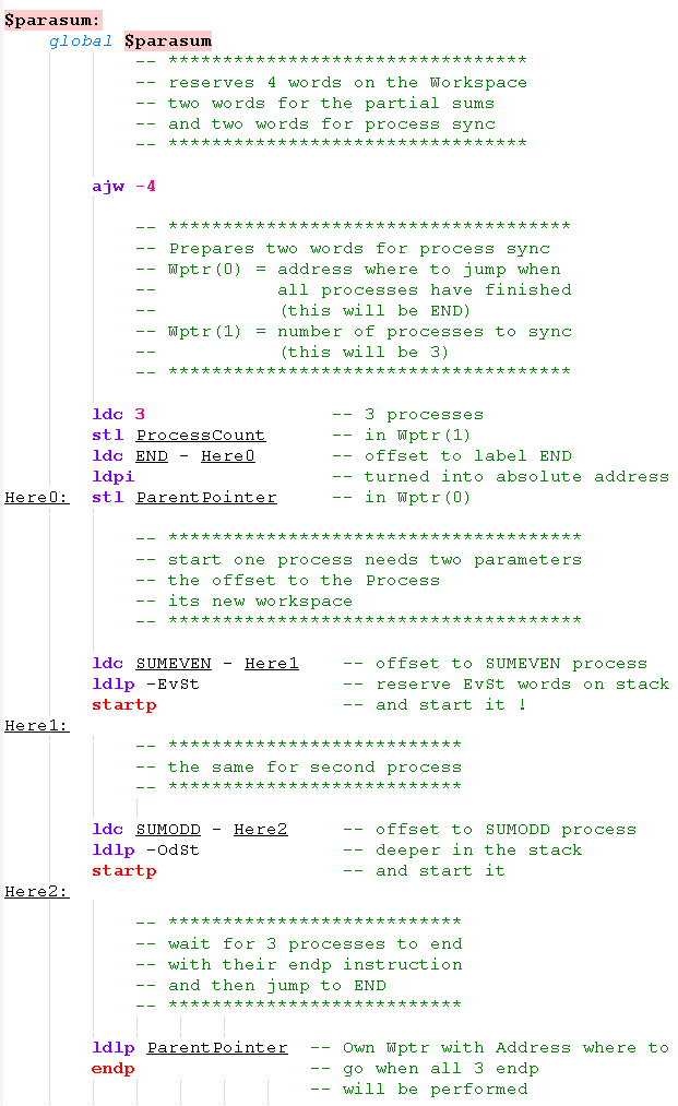
Le programme ci-contre utilise deux instructions particulières: startpqui permet de lancer un autre processus. endpqui arrête le processus en cours avec une possibilité de synchroniser la fin de plusieurs process avant de continuer. L'organigramme ci-contre montre un programme calculant la somme des entiers de 0 à n en séparant le calcul :
Le nombre de process est fixé à 3 et chaque instruction endp décrémente ce registre. Un fois arrivé à zéro, tous les programmes ont fini et l'exécution peut se poursuivre sachant que le travail a bien été synchronisé. |
|
The program presented here as an organigram, uses two particular instructions: startpthat runs another process. endpthat terminates the current process with the ability to synchronize the end of several processes before continuing. This program computes the sum of integers from 0 to n with two processes:
The number of processes is 3 in this case. Every endp instruction decrements this value. Once zero is reached, the system knows that all processes are terminated and so it can go on with the end of the program. This is a simple way to synchronize the work. |
|
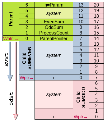
Organisation de la pile
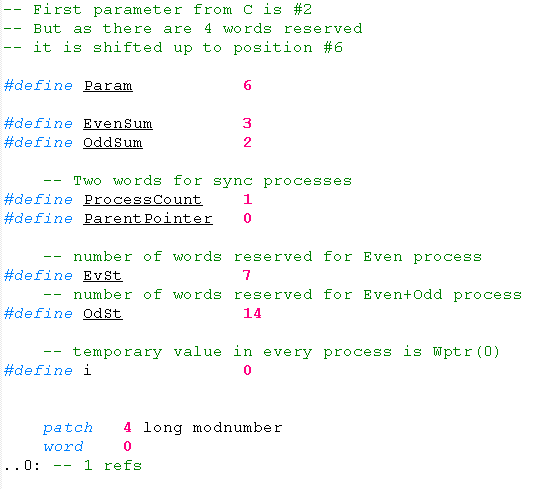
Chaque processus ayant son pointeur de pile Wptr, l'accès à une même zone se fait avec un décalage. Par exemple, la donnée Param est:
|
|
|
Stack Organization
Every process has its own stack pointer Wptr, so, access to a particular data is done with an offset from one process ton another. For example, the word Param is:
|
Autour les deux processus de somme des pairs (SUMEVEN) et impairs (SUMODD). Tous se terminent par endp pour se synchroniser. 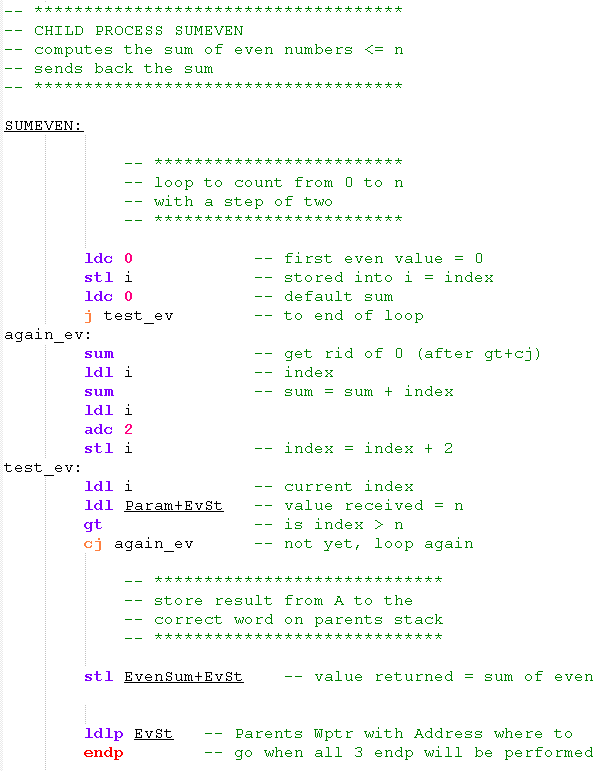
|
|
Left and right the two processes to sum the even (SUMEVEN) and odd (SUMODD) numbers. All terminate with endp to synchronize themselves. 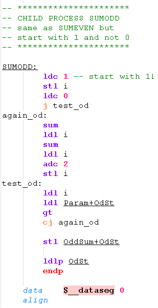
|
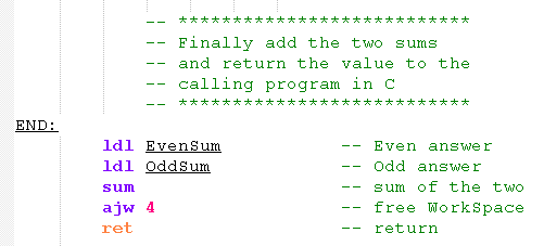
La somme totale est retournée. |
Download PARA.ZIP |
The global sum is returned. |
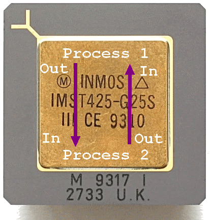
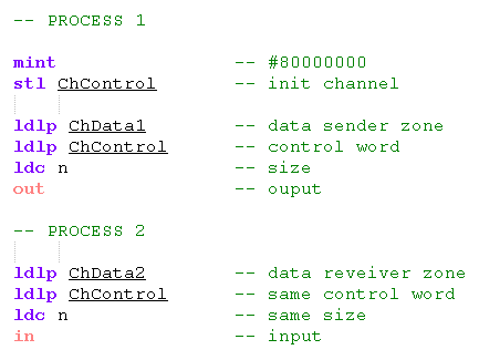
| Dans un même processeur Pour cela, le processeur gère des canaux de communication, les Channels, au niveau du langage machine directement. Là encore, pas besoin d'un système d'exploitation. Les channels utilisent principalement deux instructions: OUTqui permet d'envoyer des données et INqui permet d'en recevoir. Afin que ceci soit synchronisé, un channel est défini par un mot de controle, c'est un WORD quelque part en mémoire. Les deux processus échangeant des données doivent faire référence au même WORD de contrôle. En plus de cela, chacun fournit une adresse où sont stockées les données à envoyer ou recevoir ainsi que la taille en octets. Ci-contre, un exemple d'échange. Vous remarquez qu'au démarrage, un channel est initialisé avec la valeur hexadécimale #80000000 (que l'on obtient avec l'instruction mintqui charge en A la valeur "Minimal Integer"). |
|
Inside one only processor To acheive this, the processor manages communication channels at the machine language level, directly. There again, no need for a multitasking OS. The channels are accessed via two main instructions: OUTto send data and INto receive. To synchronize the exchange, a channel is defined by a control WORD, somewhere in memory. The two processes must refer to the same control word when sending/receiving data. In addition, each of them provides an address where to read or write data in memory and the data size in bytes. Here you can see an example of communication program. Note that a channel must be initialized with the hexadecimal value #80000000 (that we can get using mintthat stores in A the "Minimal Integer"). |
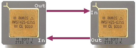
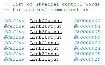
| Entre deux processeurs On remplace simplement notre mot de contrôle par l'une des huit adresses réservées au canaux physiques, appelés LINK, et qui sont au nombre de 4 sur la plupart des transputers et bidirectionnels. En modifiant simplement une adresse, on passe d'une communication interne à une communication externe. J'ai joint a titre d'exemple le même programme qu'au dessus (celui de la somme des entiers) mais en utilisant des canaux de communication entre les différents processus. |
 Download PARA-IO.ZIP |
Between two processors You just have to replace your control word by one of these height reserved addresses corresponding to the physical channels, called LINK. On most transputers, there are four bidirectionnal links. Just by modifying an address, we can switch from an internal to an external communication. As an example, you can download the same program as before (the one adding integers), but this new one uses channels to exechange data between the different processes. |
|
|
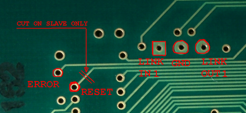
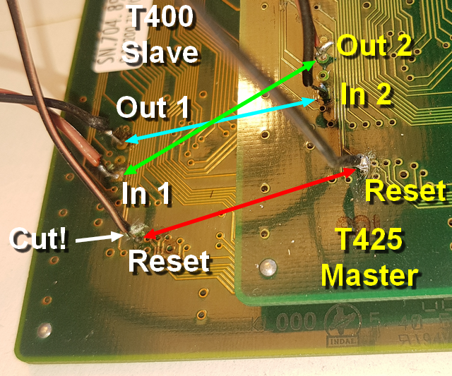
| Relier deux processeurs Il est trop difficile de travailler directement sur les broches du processeur, Mike m'a indiqué les endroits précis où se retrouvaient les signaux de communication au dos de la carte. Il n'y a plus qu'à souder. |
|
Link two processors It's really hard to work directly on the pins of the transputer. Mike showed me where to get the same signals on the back of the board in places more accessible. Now, I just had to solder. |
| Maître et esclave Le plus important est de relier les broches "LINK".
|
|
Master and slave The most important is to wire the "LINK"s.
|
| Réinstallation |
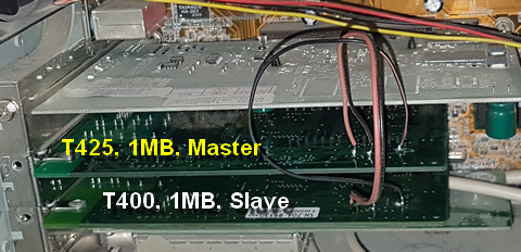
|
Back on the box |
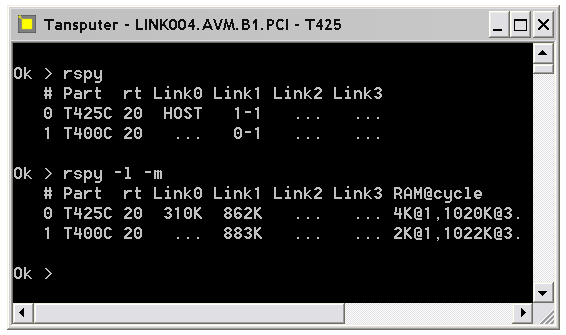
Test du réseauRSPYqui montre que les deux Transputers sont connectés. Le n°0 au n°1 et inversement sur leur Link#1. Par ailleurs, le T425 est relié au PC (HOST) sur son Link#0. Ensuite, avec la commande RSPY -l -mj'affiche les vitesses des liens et la mémoire embarquée. Les deux transputers communiquent à plus de 800ko/s et notez que le T425 dispose 4Ko de FastRam sur les 1024 ko alors que le T400 est limité à 2Ko. |
|
Net testingRSPYthat shows how the two transputers are connected. T#0 and T#1 are linked through their Link#1. Besides, the T425 is linked to the HOST PC through its Link#0. Then, with the command RSPY -l -mI get the speed and memory statistics. The two transputers communicate at a speed greater than 800kB/s and note that the T425 owns 4kB of FastRam among the 1024 kB while the T400 is limited to 2kB. |
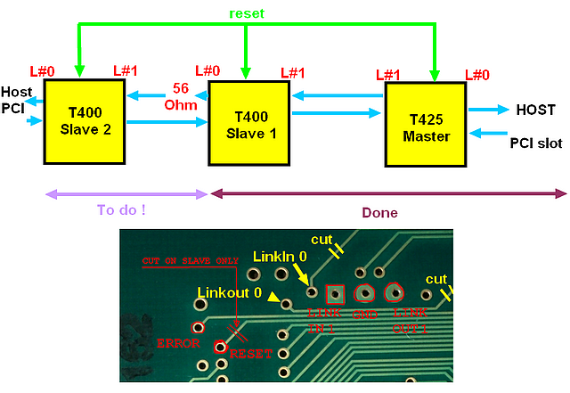
| Ajout d'un 3e processeur De ce fait, le second processeur n'a plus accès au Host et ne peut être programmé que par ses deux voisins. J'ai cherché sur la carte les points correspondants au Link#0 que j'ai fini par trouver. Reste à faire les soudures et à couper les pistes pour libérer le Link#0 du Host. Cette méthode peut s'étendre à 4 processeurs ou plus, selon le nombre de slots PCI disponibles! |
|
Adding a 3rd processor In this case, the second processor doesn't have access anymore to the Host and can only be programmed through one of its neighbours. I searched on the card the points for soldering Link#0 that I finally found. Let's solder and cut two more tracks. This method can easely be extended to 4 processors or more, according to the number of PCI slots you have. |
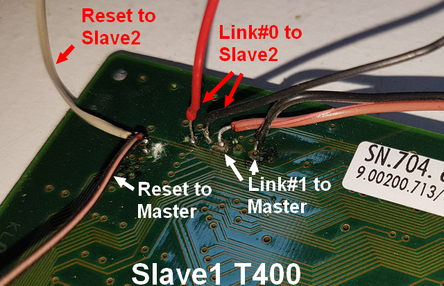
| Une carte devient centrale Elle est reliée à la fois au Master (T425) par son Link#1 et à la seconde carte Slave (T400) par son Link#0. Le contact RESET est simplement chainé vers le nouveau processeur. Sur la photo, je n'ai pas encore coupé les pistes Link#0. Note: LinkOut#0 n'a pas sa résistance de 56 Ω sur la carte, je l'a ajoutée sur le fil rouge allant vers le 3e processeur. |
|
One board becomes the center It is wired to both the Master (T425) via its Link#1 and to the second Slave board (T400) via its Link#0. The RESET point is simply chained from one processor to another. On the picture, the tracks for isolating Link#0 are not cut yet. Note: LinkOut#0 lacks its 56 Ω resistor, I had to add one on the red wire to the 3rd processor. |
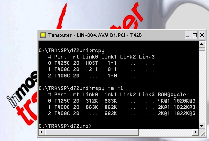
Test du réseaurspyLe réseau de trois processeurs apparaît! Les vitesses restent les mêmes. Il n'y a aucun lien direct entre le Master et le Slave2. Il faudra en tenir compte dans les programmes! C'est le T400 central qui fera le lien dans le dialogue entre les processeurs extrêmes. |
|
Net testingrspyThe 3-processor net appears! Link speeds are the same. There is no direct link between Master and Slave2. Programs should take this into account! It's up to the central T400 to make the link when the two distant processors want to talk. |
Programme de calcul de PI
|
|
PI Calculation program
|
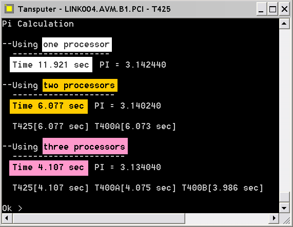
Vous trouverez ci-contre le programme en C pour le calcul de PI. |
|
Next, you'll find the PI estimation program in C language. |
| Programme de RayTracing (Johan Dams source) J'ai adapté un programme de raytracing pour qu'il tourne sur trois processeurs. Voici ici les résultats pour un calcul d'une image en 500×375 points. 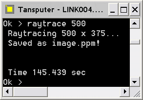 La structure est la même que celle du calcul de PI, on utilise toujours le processeur central comme pont entre le maître et le dernier processeur quine peuvent pas communiquer directement.
|

|
RayTracing program (Johan Dams source) I adapted a Raytracing program to run on three processors. Here are the results for an image of 500×375 pixels.  The structure is similar to the PI Calculation, we use the central processor as a bridge between the master CPU and the third one that can't communicate directly.
|
Lire ses articles (anglais). |
|
Read his articles. |