| Hewlett Packard HP 86B
|
 |
 |
 |
 |
 |
 |

| What's in the box? | ROM Modules | The Hard Disk | The floppies | HP-IL interface | RS232 interface | Commented example | Plotter/Emul |
 |
The ROM modules are inserted into the ROM DRAWER HP 82936A plugged into one of the four extension ports on the back panel. Unfortunately, only 6 modules can be used at a time, because only one drawer is allowed by the system. SO you have to make your choices. Each one comes with new BASIC commands or new hardware drivers. Here are the ones I use... |
 |
This module adds the support for mass storage units using the SS/80 protocol. This became a must for the last hard disk generation produces by HP as the one I use: the 9154A. See below! |
 |
This module gives access to the machine language of the computer.
It allows editing a source file, compiling it to a binary file. Then, you can load this binary from BASIC
to:
|
 |
My first program: ASQR It creates a new BASIC function ASQR(X) that returns the square root of the absolute value of X. Then, even with a negative entry, no error will be generated. Lines 1000-1050 a table with the different entry points. Every binary program must adopt this structure to be loaded. Lines 1100-1110 the PARSE routine that is supposed to read the line after the key word to get the parameters. For a function, it is useless and we can let the system manage it with the standard routine. So no parsing. Lines 1200-1290 routines table: only one function, so only one routine. Lines 1300-1390 names table, only one: ASQR. No error message. Lines 1400-1410 the INIT routine, useless for my function. Lines 3000-3040 the ASQR routine. The bytes 20 and 55 define a numeric function with one argument. Then two calls to ABS and SQR (internally, the BASIC is organized as a RPN calculator with a stack. So we are close to the HP41 way of thinking. Then a RTN to return. Lines 3050-9999 addresses definition. To end a source, use the key word "FIN", yes... in french! |
I type
ASSEMBLE "ASQR_B"to generate the binary file and then, back to BASIC. See how simple is it to load the new function and use it immediately! |
 |
 |
This modules allows you to drive plotters. The graphic language, HP-GL, is very similar to
LOGO. With pen up and down, pen color (if the plotter has several pens), relative or absolute pen position.
The instructions are the same as the one for a CRT display. So you can write the same program for a paper or video output.. Have a look at my Plotter Emulator! |
 |
This modules manages the input and output in conjunction with HP-IL or RS232 cards.
It brings a whole set of instructions for sending/receiving data and setting up the protocols.
See the THERMO example using a HP-IL link to a data acquisition peripherial. |
 |
This is a two rom module! Two ROM slots are requiered to benefit from its routines.
It brings:
|
 |
This hard drive uses the SS/80 command set (so, the Extended Mass Storage module is requiered)
and brings the huge storage space of 10MB.
It plugs into the HP-IB port and, its default value is ":D700" peripherial. |
The file system is archaic:
|
 |
| Here is the floppy unit. I set it as peripherial "1" on the GP-IB chain "7".
So, the first drive is named ":D710" and the second ":D711".
Each unit provides something as 620KB storage. This means 52 screen captures in GRAPH mode! |
 |
INITIALIZE "mydisk",":D711" STORE "myprog:D710" MASS STORAGE IS ":D710" COPY "myprog" TO "myprog:D711" |
|
| I had to disassemble the units to repair the ejection system. This is a know problem that a flat metal piece tends to stick to the shield after some years (with a mix of dust and fat). This metal part must be pushed to the back when the disk is out. (Fig 1, you can see the space between the metal and the square button). | This same part must be pulled to the front when the disk is in. (Fig 2, no space between metal and the square button). If this is not the case, drop some alcohol to the places pointed by the green arrows and gently force the piece to move. It gets rapidely unstuck and the drive is ready to work again! |

Figure 1: disk out. |

Figure 2: disk in. |
INITIALIZE "GAME",":D710" TD2HPI GALPATRL DIR *.HPI Fdio -dup GALPATRL.HPI a: CAT ":D710" COPY ":D710" TO "D711" |
|
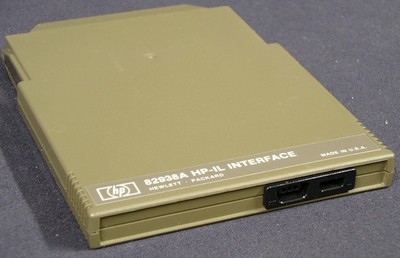 |
It allows to connect your computer to a range of peripherials for characters transferts.
|
| Unfortunately, you have to open it to set the configuration switches. Three of them
represent the interface address, default is #9. Then, the first peripherial on the loop will be
"901", the next "902", and so on.
The last switch sets the computer as the loop controller or not. Normally, it is ON, but you may experience conflicts when connected to the HP41. I didn't. |  |
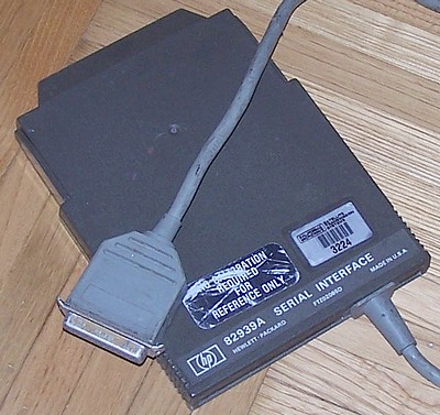 |
This serial interface allows connections with RS-232 protocol to a
printer, a modem or another computer.
It is limited to 9600 bauds, what is enough compared to the computer's speed.
Two options were available:
|
| Concerning the settings, two switches blocs are available. They set the default
values for the interface. Then, most settings can be altered by program.
The first bloc sets the interface number, default is 10. |
The second bloc sets parity, stop bits, speed and the number of bits per byte.
I set 9600 bauds, no parity, 1 stop bit and 8 bits per byte. |
 |
 |
| I linked the HP86 to a PC running Windows XP. In the DOS command line, I type: MODE COM1: BAUD=9600 PARITY=N DATA=8 STOP=1 [ENTER] COPY CON: COM1: [ENTER](This last line to copy the keybord to the serial port). |
On the HP side, I type this program:
10 DIM A$[128]
20 ENTER 10;A$
30 DISP A$
40 GOTO 20
And then the RUN key to start it! |
| On the HP86 side, you run the program SERIE (see on the right) that waits for
the transfert informations.
On the WINDOWS side, you run the program COPIE SERIE.EXE (see below) that opens a fileselector for you to specify the TEXT file you want to send. This file is parsed to count the total bytes and the number of lines to send, you must then type the name you want to use when saving the TEXT on the HP. Finally, the data (name, number of blocks, number of lines) are sent follwed by the lines themselves. On the HP display, you can see the data and then the lines one by one as they are received.  Be sure to press K1 when you are told to! |
 The reception program on the HP86 |
For a BASIC program :
|
For an ASSEMBLY source :
|
|
On the HP86 I type:
CRT IS 10 LIST This sends the whole source file to the TERMINAL where I can capture the text! | Then:
CRT IS 1 To go back to normal mode on the HP. |
| Setp 1: First, select an image with square proportions. | Setp 2: Then resize it to 400x240. | Setp 3: Then apply a monochrom filter (Stucki here). Save it to BMP. |
 |
 |
 |
| Finally, you send it to the HP. Run first "COPIE SERIE.EXE", select mode 2 to send an image
and then select the image file. "Sending lines..." is displayed.
On the HP, run the program "SERIE", key K2 to receive an image and ENTER to start transfert. 
Be sure to press K2 when you are told to! |

The image received on the HP86 !! |
To send the GRAPH screen of the HP to the PC, the image must be in memory!
You are asked for the BMP filename (don't forget to add the BMP extension) and transfer starts! Here an example of a received image:  I selected green pixels on a black background! |
 Be sure to press K3 when you are told to! |
| This monitoring program regularly captures (using a timer) two temperatures (in and out) and the ambient light
using three sensors and produces a graphic on demand.
Here is the installation: |
 |
 |
Here is the graphic produced. Data has been monitored for 1h40 with a one minute step. It was a sunny morning with some clouds (look at the variations of light on the photoresistor curve). External temperature variations are close to the light variations while the internal temperature grows regularly. |
|
Lines 10-30: the function that converts resistance to temperature, NOIR and BLANC (blck and white) are the empirical extrem values for the LOG(light resistance), and then the table with T(0,i) for inside temperature, T(1,i) outisde one and T(2,i) the light. Lines 100-230: initialisation, then sets the Timer for data aquisition, and sets the three keys actions. Line 500: event loop waiting for a timer or a key. Lines 1000-1090 (Timer #1): send command through HP-IL, ask for reading resistance channels 2,3 et 4. Retreives data in B, C et A. Values are converted, displayed, stored into the table and min/max updated. Lines 2000-2010 (Key F2): graph mode, clears screen. LOCATE sets the plotting area to let some room for axes and labels. Line type is 1, solid. Lines 2020-2040: I and X and the integer limits for temperature. SCALE defines the actual values for axes. LAXES draws the axes with labels. Lines 2050-2100: The double loop draws the two temperature curves directly using values in time and temperature as defined by SCALE. The system manages the conversion in pixels. Lines 2110-2125: a new scale to adapt screen for light values. (The highest value NOIR is set for Ymin. This way, high resistance will appear on the bottom of the graphic as it represents a low light). Line type set to 2, dots! Lines 2030-2060: draws the light curve. Lines 3000-3020 (Key F1): back to text page. Lines 4000-4050: Initialization, displays title and ask for the time step in hour-minute-second. Lines 4060-4075: computes the interval IT in seconds and MS in milliseconds (for the Timer), set initial values for min and max temperature and ligh. Lines 4080-4090: If no second are given then turns the intervall to minutes for labelling. Then if no minute, turn the interval to hours for a better labelling. Lines 4100-4110: the GOSUB gets the first measurement and back to event loop. Line 5000 (Key F7) : program end! |
 |
 |
Here is the text page with retreived data. Note the buttons on the bottom of the screen, they are automatically set up by the system with ON KEY. This allows you to easely create a menu. Text and graphic pages are independant and you don't clear the one when you display the other. The A/G key (Alpha/Graphics) swaps the pages. |
| On the HP86 side, you need a serial interface with 9600 bauds, 1 stop bit, no parity, and 7 bits data. Plotting is redirected to the serial interface. | CONTROL 10,4;4 -> for 7 bits CONTROL 10,3;15 -> for 9600 bauds PLOTTER IS 10 -> insert this in your program |
 |
 |
 |
Download it! |
Now you can RUN the HP86 program (the plotter must be on line to answer to the "PLOTTER IS 10" statement that need informations). |
The file name will be PLOTTER_00000.PNG and following numbers for next pages. |
| Here is the plotting result. I used the example that can be found in the Plotter module manual, note that plotting is in colors inserting PEN n commands to change the pen color. Note: another file is created, PLOTTER.TXT, containing all the instructions received, the pages saved, etc... |
 |
| Plotter HP 7550A I got a HP 7550A, 8 pens plotter, that allows to display on A4 or even A3 paper. I wrote a little program to plot the backgound of my genealogy trees over 8 generations. For now, I have to fill them by hand, but who knows, I could prepare a data base with all names and plot them directly from the HP. |

|